Patent Office
by Dick Bowman
Reprinted from "Crown Jewels of the Wire", October 1996, page 4
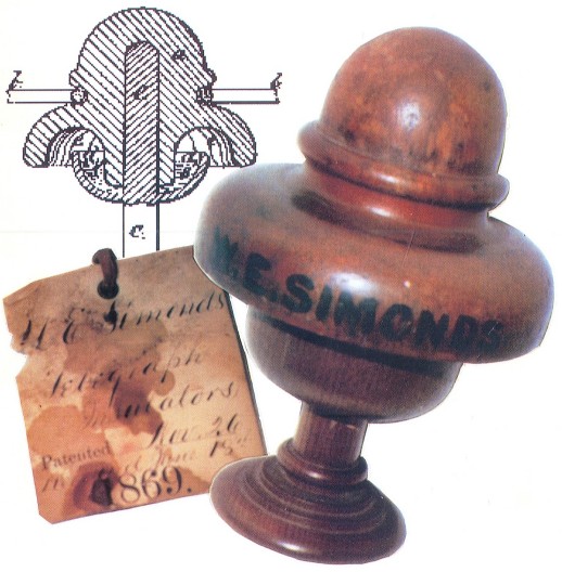
W. E. SIMONDS Telegraph Insulator
The insulator model of a telegraph insulator patented November 26, 1867 by
W.E. Simonds, along with the papers, were acquired by me late this past spring
in New England after having seen the model earlier in the year near Buffalo, New
York. I have no reason to think that Mr. Simonds insulator was ever put into
production.
The wooden model stems from the requirement in the earlier days of the U.S.
patent laws that every application for a patent must be accompanied by a model
no larger than 12" by 12". Obviously, for many years that requirement
has been outmoded and invalid. Most of these models were made by professional
model makers and I am sure this is no exception as it is a high quality piece of
work in cherry or walnut.
As you can see from the picture on the front cover and from the patent papers
which follow, it was designed to be a two piece insulator with the top piece
apparently being secured to and into the inverted cup type bottom piece with, as
Mr. Simonds suggests, India rubber, rubber cloth or other flexible
non-conducting material. Would this method have worked, or did it work during
possible subsequent tests? Perhaps not, as I discovered while taking the
pictures for this article.
As I was removing the patent tag which reads: 71,418 W. E. Simonds.
Telegraph Insulator. Patented November 26, 1867 from a plastic sleeve which
was attached to the wooden model, I discovered a second patent tag underneath
the 1867 tag. This tag made reference to telegraph insulators (plural) by
W.E. Simonds. This tag, pictured on the cover, reads: W. E. Simonds.
Telegraph Insulators. Patented Nov. 26 (no year-assume 1867) Received June 18th
1869. I dragged out my 1972 books on insulator patents put together by Aubrey
& Penney Branham and, lo and behold, found a copy of the patent papers dated
June 29, 1869 by the same W. E. Simonds. It seems that the original tag and
model for the 1867 patent may have been resubmitted at the time of the 1869
patent application and a second tag attached to the model. Or, for filing
purposes, all of Simonds paperwork stayed together until I purchased them.
As you can see, Mr. Simonds shows and describes both a pintype and a hook or
ramshorn type insulator, each having the inverted cup at the base. The pintype
is practically identical in appearance to the one shown in 1867, but the cup now
is described as being filled with paraffin or some other non-conducting or
insulating substance. This principle can also be noted in the birdfeeder style
battery insulators when oil was apparently used.
Medium Image (43 Kb)
Large Image (104 Kb)
Large Image (295 Kb)
|
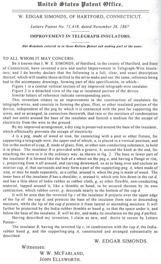
(text from above image)
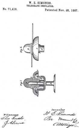
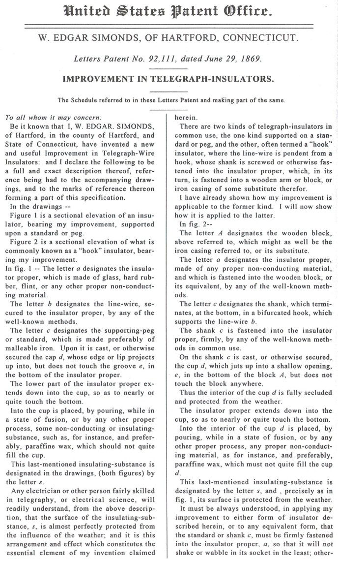
United States Patent Office.
W. EDGAR SIMONDS, OF HARTFORD, CONNECTICUT.
Letters Patent No. 71,418, dated November 26, 1867.
IMPROVEMENT IN TELEGRAPH-INSULATORS.
The Schedule referred to in these Letters Patent and making part of the same.
TO ALL WHOM IT MAY CONCERN:
Be it known that I, W. E. SIMONDS, of Hartford, in the county of Hartford,
and State of Connecticut, have invented a new and useful Improvement in
Telegraph-Wire Insulators; and I do hereby declare that the following is a full,
clear, and exact description thereof, which will enable those skilled in the art
to make and use the same, reference being had to the accompany drawings, forming
part of this specification, in which--
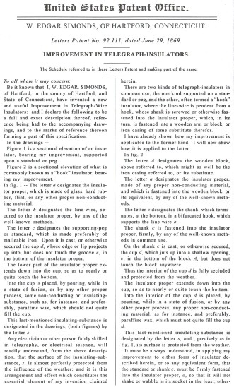
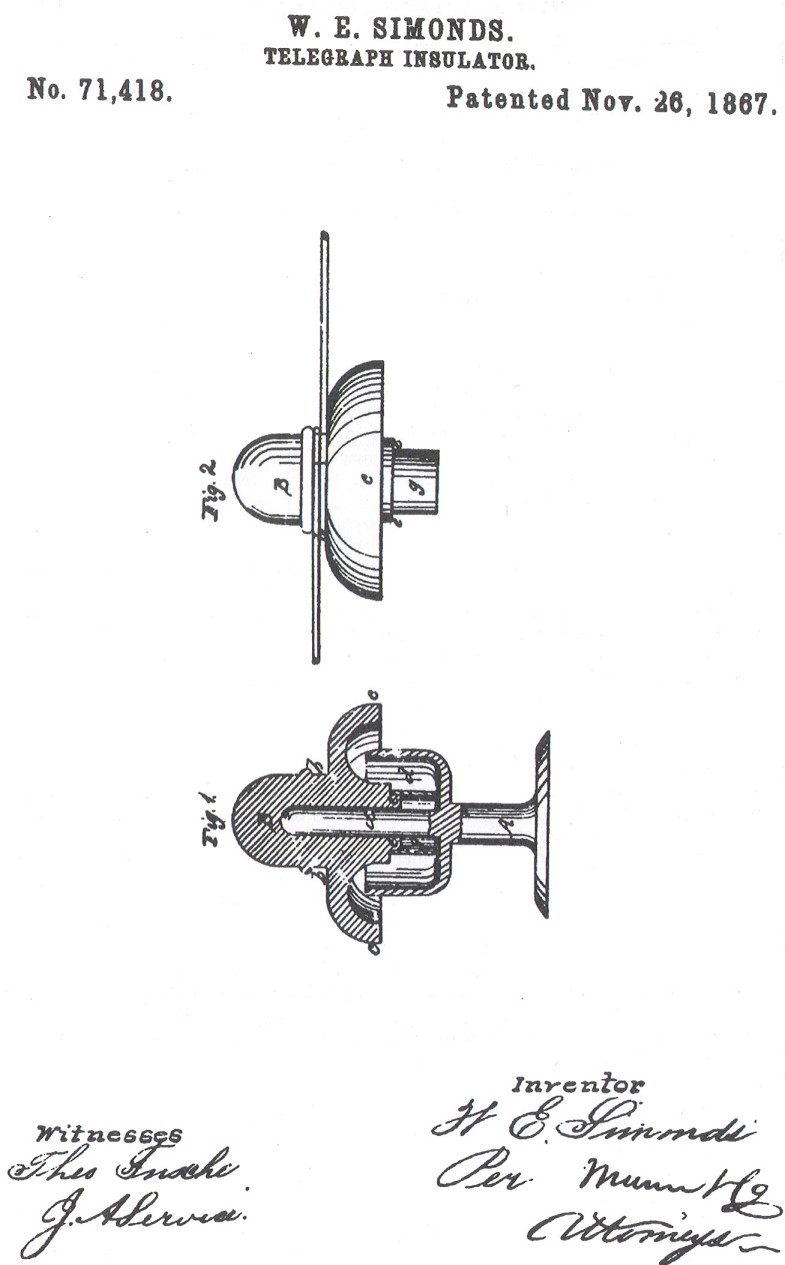
Figure 1 is a central vertical section of my improved telegraph-wire
insulator.
Figure 2 is a detached view of the cap or insulated portion of the device.
Similar letters of reference indicate corresponding parts.
This invention relates to an improvement in the construction of insulators
for telegraph-wires, and consists in forming the glass, flint, or other
insulated portion of the device, independent of the peg by which it is connected
with the post for supporting the wires, and so arranged, in connection
therewith, that rain or the moisture of condensation shall not settle around the
base of the insulator and furnish a medium for the escape of electricity from
the wire to the ground.
By my improved arrangement, a dry ring is preserved around the base of the
insulator, which effectually prevents the escape of electricity.
A is a peg, made of wood or iron, for connecting with a post or other
fixture, for supporting a telegraph-wire, the upper end of which, a, is placed
in a vertical position, and fits in the socket of a cap, B, made of glass,
flint, or other non-conducting substance, to hold it in place. The insulator B
is provided with a groove, b, around the knob at the end, for attaching the wire
to it in the ordinary way, as shown in fig. 2. The base or lower part of the
insulator B is formed like the hub of a wheel on the peg a, and having a flange
or rim, c, projecting from it all around, and curving downward, so as to hang
over and enclose an interior cup, d, that surrounds and may form a part of the
supporting-peg A, when made of iron, or may be made separately, as a collar,
around it, when the peg is made of wood. The inner base of the insulator B has a
shoulder, e, around it, which sets low down in the cut d, and has a thin sheet
of India rubber or rubber cloth, g, or other flexible, non-conducting material,
lapped around it, like a thimble or hood, to be secured thereon by its own
contraction, which rubber cover, g, descends nearly to the bottom of the cup d.
It will be seen that the inverted lip c of the insulator B projects over the
upper edge of the lip of the cup d, and protects the base of the insulator from
rain or descending moisture, while the lip of the cup d protects it from lateral
or ascending moisture. It will further be protected by the India-rubber thimble
or hood g, so that the space under it, and below the base of the insulator, B,
will be dry, and make its insulation on the peg A perfect.
Having described my invention, I claim as new, and desire to secure by
Letters Patent--
The insulator B, having the inverted lip c, in combination with the cup d,
the India-rubber hood g, and the supporting-peg A, constructed and arranged
substantially as described.
W. EDGAR SIMONDS.
Witnesses:
W.W. MCFARLAND,
JOHN ELLSWORTH.
|
Medium Image (76 Kb)
Large Image (186 Kb)
Large Image (301 Kb)
Large Image (178 Kb)
|
(text from above images)
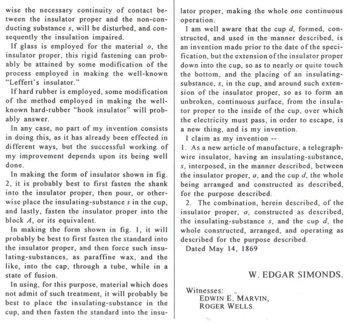
United States Patent Office.
W. EDGAR SIMONDS, OF HARTFORD, CONNECTICUT.
Letters Patent No. 92,111, dated June 29, 1869.
IMPROVEMENT IN TELEGRAPH-INSULATORS.
The Schedule referred to in these Letters Patent and making part of the same.
To all whom it may concern:
Be it known that I, W. EDGAR. SIMONDS, of Hartford, in the county of
Hartford, and State of Connecticut, have invented a new and useful Improvement
in Telegraph-Wire Insulators: and I declare the following to be a full and exact
description thereof, reference being had to the accompanying drawings, and to
the marks of reference thereon forming a part of this specification.
In the drawings --
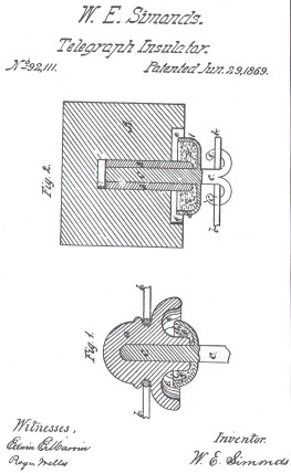
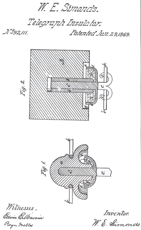
Figure 1 is a sectional elevation of an insulator, bearing my improvement,
supported upon a standard or peg.
Figure 2 is a sectional elevation of what is commonly known as a hook
insulator, bearing my improvement. In fig. 1 -- The letter a designates the
insulator proper, which is made of glass, hard rubber, flint, or any other
proper non-conducting material.
The letter b designates the line-wire, secured to the insulator proper, by
any of the well-known methods.
The letter c designates the supporting-peg or standard, which is made
preferably of malleable iron. Upon it is cast, or otherwise secured the cap d,
whose edge or lip projects up into, but does not touch the groove e, in the
bottom of the insulator proper.
The lower part of the insulator proper extends down into the cup, so as to
nearly or quite touch the bottom.
Into the cup is placed, by pouring, while in a state of fusion, or by any
other proper process, some non-conducting or insulating-substance, such as, for
instance, and preferably, paraffine wax, which should not quite fill the cup.
This last-mentioned insulating-substance is designated in the drawings, (both
figures) by the letter s.
Any electrician or other person fairly skilled in telegraphy, or electrical
science, will readily understand, from the above description, that the surface
of the insulating-substance, s, is almost perfectly protected from the influence
of the weather; and it is this arrangement and effect which constitutes the
essential element of my invention claimed herein.
There are two kinds of telegraph-insulators in common use, the one kind
supported on a standard or peg, and the other, often termed a hook
insulator, where the line-wire is pendent from a hook, whose shank is screwed or
otherwise fastened into the insulator proper, which, in its turn, is fastened
into a wooden arm or block, or iron casing of some substitute therefor.
I have already shown how my improvement is applicable to the former kind. I
will now show how it is applied to the latter.
In fig. 2--
The letter A designates the wooden block, above referred to, which might as
well be the iron casing referred to, or its substitute.
The letter a designates the insulator proper, made of any proper
non-conducting material, and which is fastened into the wooden block, or its
equivalent, by any of the well-known methods.
The letter c designates the shank, which terminates, at the bottom, in a
bifurcated hook, which supports the line-wire b.
The shank c is fastened into the insulator proper, firmly, by any of the
well-known methods in common use.
On the shank c is cast, or otherwise secured, the cup d, which juts up into a
shallow opening, e, in the bottom of the block A, but does not touch the block
anywhere.
Thus the interior of the cup d is fully secluded and protected from the
weather.
The insulator proper extends down into the cup, so as to nearly or quite
touch the bottom. Into the interior of the cup d is placed, by pouring, while in
a state of fusion, or by any other proper process, any proper non-conducting
material, as for instance, and preferably, paraffine wax, which must not quite
fill the cup d.
This last-mentioned insulating-substance is designated by the letter s, and ,
precisely as in fig. 1, its surface is protected from the weather. It must be
always understood, in applying my improvement to either form of insulator
described herein, or to any equivalent form, that the standard or shank c, must
be firmly fastened into the insulator proper, a, so that it will not shake or
wabble in its socket in the least; otherwise the necessary continuity of contact
between the insulator proper and the non-conducting substance s, will be
disturbed, and consequently the insulation impaired.
If glass is employed for the material o, the insulator proper, this rigid
fastening can probably be attained by some modification of the process employed
in making the well-known Lefferts insulator.
If hard rubber is employed, some modification of the method employed in
making the well-known hard-rubber hook insulator will probably answer.
In any case, no part of my invention consists in doing this, as it has
already been effected in different ways, but the successful working of my
improvement depends upon its being well done.
In making the form of insulator shown in fig. 2, it is probably best to first
fasten the shank into the insulator proper, then pour, or otherwise place the
insulating-substance s in the cup, and lastly, fasten the insulator proper into
the block A, or its equivalent.
In making the form shown in fig. 1, it will probably be best to first fasten
the standard into the insulator proper, and then force such
insulating-substances, as paraffine wax, and the like, into the cap, through a
tube, while in a state of fusion.
In using, for this purpose, material which does not admit of such treatment,
it will probably be best to place the insulating-substance in the cup, and then
fasten the standard into the insulator proper, making the whole one continuous
operation.
I am well aware that the cup d, formed, constructed, and used in the manner
described, is an invention made prior to the date of the specification, but the
extension of the insulator proper down into the cup, so as to nearly or quite
touch the bottom, and the placing of an insulating-substance, s, in the cup, and
around such extension of the insulator proper, so as to form an unbroken,
continuous surface, from the insulator proper to the inside of the cup, over
which the electricity must pass, in order to escape, is a new thing, and is my
invention.
I claim as my invention --
1. As a new article of manufacture, a telegraph-wire insulator, having an
insulating-substance, s, interposed, in the manner described, between the
insulator proper, a, and the cup d, the whole being arranged and constructed as
described, for the purpose described.
2. The combination, herein described, of the insulator proper, a, constructed
as described, the insulating-substance s, and the cup d, the whole constructed,
arranged, and operating as described for the purpose described.
Dated May 14, 1869
W. EDGAR SIMONDS.
Witnesses:
EDWIN E. MARVIN,
ROGER WELLS.
|
Did either style work and/or did the 1869 modification prove functional? That
may be the subject for some later work or research, but in the meantime I will
continue to enjoy my addition to the Americana on my shelves. The question that
begs asking is whether subsequent models were made to accompany the 1869 patent
or was the 1867 model deemed adequate to illustrate Mr. Simonds principle. I
now have some work to do to see if a later model can be unearthed.
|

)
)